Radio
transmitters that utilize tall antenna towers are particularly
vulnerable to lightning strikes because these towers closely
resemble lightning rods, designed to conduct lightning energy
to ground. A session at this year’s NAB Broadcast Engineering
Conference (BEC, April 18-23, 2009, Las Vegas, NV) entitled
“Towers and Transmission Systems Part II” included
a paper, excerpted here, which presents a simplified summary
of lightning data from several technical sources and then goes
on to discuss protection principles, concluding with specific
system recommendations.
LIGHTNING
INCIDENCE AND TYPICAL CHARACTERISTICS – the amount
of time, effort and money that should be afforded to lightning
protection depends upon a number of factors including the equipment
value, the importance of continuity of service and the frequency
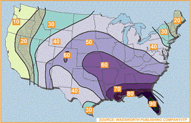
of lightning storms in the particular geographic region. The
incidence of electrical storms without regard to their type
for the U.S. is shown in the figure below (numbers and shading
indicate mean annual number of days with thunderstorms). It
may be seen that in the U.S., peak incidence occurs in central
Florida and extending over the southern states.
The
main stroke of a lightning strike is characterized by a rapid
rise and near-exponential decay of current, essentially from
a high impedance source comprised of a long length of ionized
air. Presumably the inductance of the air path determines the
rate of rise of the current and the resistance determines the
current peak value and decay rate. Pulse characteristics vary
widely from strike to strike. Rise times of 0.1-20 µs
with exponential decays of 20-100 µs have been reported
with peak amplitudes between 20,000 and 120,000 amps.
PROTECTION
PRINCIPLES – if lightning strikes a radio tower with
local grounding either directly (grounded tower) or via a spark
gap (insulated tower) then the large current pulse flowing through
the local ground impedance would develop a very high potential
with respect to ideal ground. For example, with a median current
pulse of 20,000 amps and an impedance to ideal ground of 50
ohms, this potential would be one million peak volts. In essence,
the entire transmitter site becomes elevated to this potential
for the duration of the lightning pulse. If now the antenna
local ground is connected via surface cabling to remote grounds,
then a substantial part of the discharge current could flow
through this path, which generally includes the shield of the
antenna feed cable or any other wiring that interconnects the
base of the antenna with the transmitter building, straight
through the transmitter and into the ac line supply.
Consequently,
the first and most important principle is to provide the best
possible (lowest impedance) local ground at the base of the
antenna. It cannot be assumed that the antenna ground mat has
a low impedance to ideal ground. It may function as a good counterpoise-type
ground return at the operating RF frequency yet have high resistance
to ground. The ground mat must be supplemented by one or more
driven ground rods. The second principle is that this current
must not flow through the transmitter itself. [Arrangements
whereby a safe path is provided through a suitably located surge
arrester, into the ac line supply, bypassing the transmitter
are shown in the full paper.]
TRANSMITTER
BUILDING LAYOUT – the geometry of the interconnections
in and around the transmitter building is critical to the effectiveness
of the lightning protection system. The ideal arrangement is
to bring all electrical conductors that connect to the building
in close proximity to each other at a location designated as
the station reference ground. Appropriate surge protection devices
are installed at this location, providing a safe path for the
lightning current that does not include the interior of the
building. This technique is commonly used with shielded rooms
that are used to test sensitive electronic equipment. Where
remedial measures are to be applied to an existing building,
it is seldom possible to achieve this ideal arrangement and
some sort of compromise is necessary. Although the principles
presented in this paper are quite easy to understand, it is
often quite confusing when trying to apply them to improve an
existing building layout. The author has found it useful to
start at the antenna, then to explore all possible paths leading
to the ac line supply to assess their destructive potential.
This
paper is authored by John R. Pinks, Nautel, and is included
in its entirety in the 2009 NAB Broadcast Engineering Conference
Proceedings, available on-line from the NAB Store (www.nabstore.com).
Audio recordings of the BEC sessions are also available for
purchase – for more information, visit the NAB Show Online
Learning Center at www.softconference.com/nab.
For additional conference information visit the NAB Show Web
page at www.nabshow.com.

The May 4, 2009 Radio TechCheck is also available
in an Adobe Acrobat file.
Please
click
here to read the Adobe Acrobat version of Radio TechCheck