
|
New NRSC Guideline Provides FM IBOC Total Digital Power Values As a result of the FCC's authorization earlier this year of elevated power levels for FM in-band/on-channel (IBOC) digital sidebands, most FM broadcasters using the HD Radio IBOC digital radio system have a significant number of options when it comes to selecting digital sideband power level. To help sort out some of the details, the National Radio Systems Committee (NRSC, www.nrscstandards.org) has just published a new guideline to give broadcast engineers an easy-to-use, quick method for determining an FM IBOC station's authorized digital sideband power level based upon the station's operational configuration. NRSC-G202, FM IBOC Total Digital Sideband Power for Various Configurations, is the third NRSC Guideline developed by the NRSC's Digital Radio Broadcasting (DRB) Subcommittee. This new document is a companion to NRSC-G201-A, NRSC-5 RF Mask Compliance: Measurement Methods and Practice, and expands upon information contained in Annex 1 of that earlier document. Both of these Guidelines are available for download free-of-charge on the NRSC's Web page. NRSC-G202 is intended as an aid to those who are responsible for or involved with FM IBOC facility design, operation and compliance monitoring. A companion, web-based total digital signal power calculator tool (also available on the NRSC Web site) has been designed by the NRSC with assistance from broadcast engineering consulting firm of Cavell, Mertz and Associates. There are two principal parts to the NRSC-G202 Guideline. The first part helps a broadcaster determine a station's authorized total digital sideband effective radiated power (ERP) with respect to the licensed analog ERP for an FM hybrid or extended hybrid IBOC signal. This information is presented in a series of tables, the first set for the case of symmetric digital sidebands and the second set for asymmetric sideband operation (see the October 11, 2010 issue of Radio TechCheck for additional information about asymmetric sideband operation). 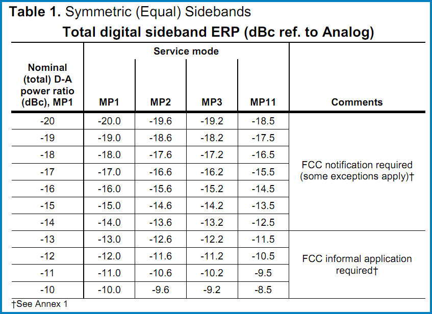
A portion of Table 1 from NRSC-G202 is shown here (the other part of Table 1 is similar but lists the total digital sideband ERP as a percentage of analog ERP rather than a dBc value). To use this table, a broadcaster first identifies the station's particular digital sideband configuration with respect to service mode (either the hybrid MP1 mode or one of the extended hybrid modes MP2, MP3 or MP11) and the desired total digital sideband power level. The actual power levels used will depend on a variety of factors including the station's equipment capabilities, the proximity of the station to first-adjacent channel signals and whether a station is considered to have "super-B" status. Once these parameters have been identified, the broadcaster can then simply find the appropriate row and column in this table corresponding to their station's operation, and read off the total digital sideband ERP for that case. Tables 2 through 5 provide similar information for the case where a station is operating with asymmetric digital sidebands (at present, operation with asymmetric sidebands requires an experimental authorization from the FCC). When using the asymmetric sideband tables, there is a potential point of confusion involving how the power level of each individual sideband is referenced. Broadcasters are used to referring to FM IBOC digital sideband power levels in the symmetric case by the total power, for example, the blanket authorization level of -14 dBc or the original authorized level of -20 dBc. In these symmetric cases, the power level of each individual sideband is actually one-half of this total (since the sidebands are symmetric), resulting in individual sideband power levels of -17 dBc and -23 dBc, respectively (for the two examples given). 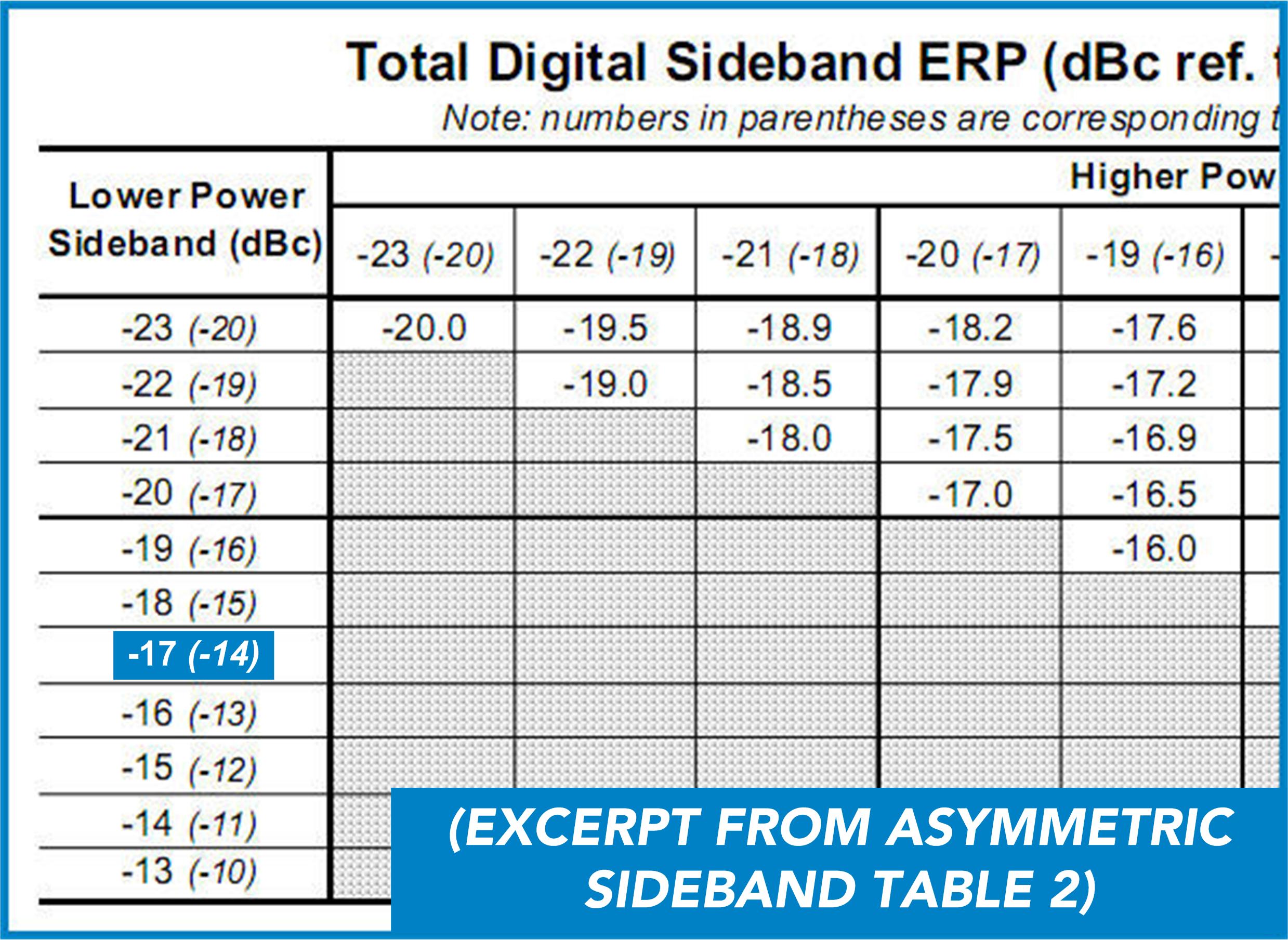
Consequently, in the asymmetric sideband tables, two power level values are provided for each entry - the actual power level of the individual sideband, and in parentheses, the corresponding power level for the symmetric case. For example, if a broadcaster is operating with the lower sideband at the equivalent of -14 dBc total power, the actual lower sideband power is 3 dB lower, at -17 dBc. For this case, the power level values in the table are written like this: -17 (-14) (as shown in the excerpt from Table 2 at right). The second part of this new Guideline provides the expected digital sideband power spectral density (PSD) for various sideband configurations. Broadcasters typically verify the digital sideband levels of an FM IBOC transmission using a spectrum analyzer (the NRSC-G201-A Guideline provides detailed information on how to make these measurements). Listed in Table 6 of NRSC-G202 are the expected digital sideband power spectral density (PSD) levels as observed on a spectrum analyzer (using the methods of NRSC-G201-A) for digital sideband power ratios from -20 dBc to -10 dBc. 
To use this table, the broadcaster first identifies the desired power ratio (relative to analog) of the digital sideband to be measured. In the symmetric case the total power ratio is used, while in the asymmetric case, the corresponding total sideband power in the symmetric case, not the actual sideband power level, is used. Referring to the discussion above, the number of interest for the asymmetric sideband case would be the number in parentheses from the appropriate asymmetric sideband table. Additional information about the NRSC including how to become a member is available from the NRSC Web page at www.nrscstandards.org. |
|
The November 1, 2010 Radio TechCheck is also available in an Adobe Acrobat file. Please click here to read the Adobe Acrobat version of Radio TechCheck. |