
|
New Method for High Level IBOC Combining Described at NAB Show As noted in the April 23, 2012 edition of Radio TechCheck, a new high efficiency FM analog/IBOC diplexer was described in a presentation at the NAB Broadcast Engineering Conference at the 2012 NAB Show. A companion technical paper entitled “High Level IBOC Combining Methods for Single Input Antenna Systems” authored by Nicholas A. Paulin and Thomas B. Silliman, P.E., Electronics Research, Inc., excerpted below, is included in the 2012 NAB Broadcast Engineering Conference Proceedings. INTRODUCTION THEORY
OF OPERATION This module
is typically inserted just before a filter or just after an exciter
to provide extra correction at high power levels. For this new device,
a different tuning method is used on this existing technology. Instead
of stagger tuning the notch filters to create a response to correct
for group delay, the notch filters are tuned identically to provide
the same group delay and same notch depth. This insures that the
short circuit seen by the hybrid is the same. When this approach
is taken, the 90 degree hybrid coupler is capable of maintaining
an excellent input VSWR while passing a high percentage of the power
to the output port. Since there are two sidebands for HD, two of
these modules are required to accomplish the performance required.
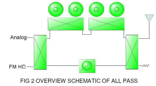
A constant impedance effect is typically used on band pass filters.
This is done by carefully tuning two filters so they match as closely
as possible for return loss and insertion phase. The filters are
then connected together by two 90 degree hybrids. The hybrids allow
several things to occur. First, the power is split so each filter
only sees 50% of the power. Second, all of the power enters one
port and exits an opposite port on the second hybrid. The remaining
two ports are isolated and see very little power. This concept has
been adapted to the all-pass circuit. By connecting the two group
delay modules and placing them in the same leg of a constant impedance
circuit, we can insure that the group delay modules only see half
of the input power. As stated earlier, a shallow notch is used to
produce the desired response. As a system, the losses will only
be half that of the tuned notches because only ½ the applied
power incurs losses in the group delay modules. This is important
since group delay modules typically produce heat. The second leg
of the constant impedance circuit can be connected by using a critical
length of transmission line. This line can be phased so that the
analog and digital insertion loss is minimized. DATA
COMPARISON The complete paper is included in its entirety in the 500+ page 2012 NAB Broadcast Engineering Conference Proceedings, available online from the NAB Store (www.NABStore.com) as a book+CD-ROM combination or CD-ROM-only version. |
|
|


ADVERTISEMENTS